Summary
The Natural Environment Research Council (NERC) Mesospheric-Stratospheric-Tropospheric (MST) Radar at Aberystwyth, a 46.5 MHz Doppler beam swinging instrument, was constructed in 1989/1990. The RF hardware has remained virtually unchanged ever since. As reported at MST12, the performance had noticeably decreased in recent years and a detailed review of the entire system was undertaken in late 2008 with a view to carrying out an upgrade. The review identified the beam steering system as an important contributor to system performance degradation and also to increased maintenance cost.
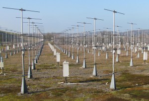
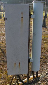
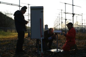
Figure 1. Part of the Aberystwyth antenna array showing the original Phase Shifter units
In February 2010 ATRAD was awarded a contract to replace the beam steering components at Aberystwyth with an upgraded system providing enhanced beam steering capability and new system monitoring features.
After a preliminary site inspection in March 2010 to verify the original MST radar’s configuration and performance was compatible with the proposed upgrade, the new system was designed, constructed and successfully installed in March 2011.
This renovation led to a remarkable 28% increase in the overall availability of horizontal wind data relative to pre-renovation levels.
The original beam steering system
The original system consisted of 3 major components:
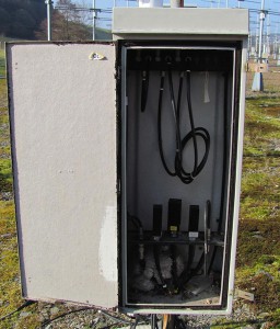
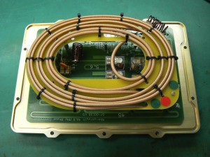
Figure 2. An original Phase Shifter unit showing the 3 delay cables and the hybrid loads for the 4-Way Splitter.
1. 100 Phase Shifter units each using 3 coaxial relays to switch in binary weighted cable delays (180,90 and 45 degrees). Each Phase Shifter drove 4 adjacent antennas via an external 4-way power splitter. The 3 hybrid balance resistors required by the Splitters were housed in the Phase Shifter boxes. (Figures 1, 2 and 3)
2. Each Phase Shifter had a multi-wire cable to the central radar hut. The cables provided power to the 3 relay solenoids and also connection to “tell-back” contacts on the relays which were intended to provide confirmation of correct relay operation. The “tell-back” feature proved too unreliable to provide useful maintenance diagnostic information.
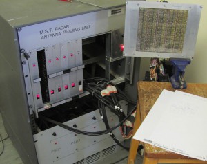
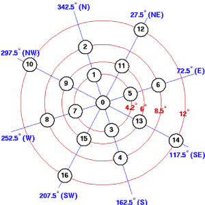
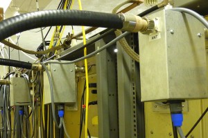
3. In the radar hut the 100 individual control cables were connected to an “Antenna Phasing Unit” (Figures 4 and 5). This unit translated a 4-bit “beam select” signal from the radar control computer into the required phase shift relay drives via a PROM-based look-up table. The antenna array geometry and the use of 3-bit Phase Shifters meant that only 17 beam directions were realistically available, of which 16 were mapped into the 4-bit control word. (Figure 6)
[wpcol_1third id=”” class=”” style=””]
[/wpcol_1third] [wpcol_1third id=”” class=”” style=””]
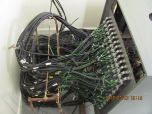
Figure 5. Rear view of the original “Antenna Phasing Unit” showing the 100 interface cables to the Phase Shifters.
[/wpcol_1third] [wpcol_1third_end id=”” class=”” style=””]
[/wpcol_1third_end]
The upgraded beam steering system:
The new system consists of 4 major components:
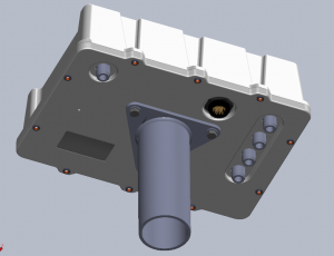
1. 100 new “smart” Phase Shifters with 6-bit precision (5.6 degree phase step size) and added monitoring and diagnostic capabilities (Figures 7 and 8).
2. The new system makes use of the existing radar antenna array’s coaxial network to provide power and control communications (2.4GHz Zigbee) to the new Phase Shifters. To couple the DC and 2.4GHz signals to the antenna array network, custom-designed multi-couplers were added to the existing 5 radar antenna array feed points.(Figure 9)
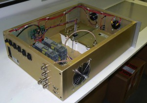
3. A new Beam Controller unit provides the DC power for the beam steering system and translates the Zigbee communications to a USB serial protocol. (Figure 10)
4. A standard Industrial PC interfaces between the USB serial protocol and a TCP/IP Ethernet connection to the existing Radar Control computer. This PC also logs diagnostic information from the beam steering system and hosts a web-page interface to provide maintainers with graphical displays of the system status.
[wpcol_1half id=”” class=”” style=””]
[/wpcol_1half] [wpcol_1half_end id=”” class=”” style=””]
[/wpcol_1half_end]
[wpcol_1half id=”” class=”” style=””]
[/wpcol_1half] [wpcol_1half_end id=”” class=”” style=””]
[/wpcol_1half_end]
Installation of the upgraded system
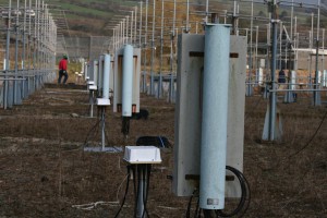
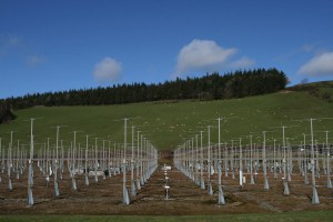
The original Phase Shifter units and their associated 4-way Splitters were removed and replaced by the new Phase Shifter units (Figures 11 and 12). The original control cables were removed. Part of the original RF cabling which was made from RG-213 coaxial cable and had suffered from deterioration and vermin damage was removed and replaced with new Heliax cables. All hardware removed in the renovation was sent for recycling and/or approved disposal. (Figure 13). Figure 14 shows a view of the antenna array after installation.
[wpcol_1half id=”” class=”” style=””]
[/wpcol_1half] [wpcol_1half_end id=”” class=”” style=””]
[/wpcol_1half_end]
[wpcol_1half id=”” class=”” style=””]
[/wpcol_1half] [wpcol_1half_end id=”” class=”” style=””]
[/wpcol_1half_end]
Features of the upgraded system:
The new Phase Shifter units incorporate an embedded micro-controller module with on-board Zigbee network interface and ADC. This approach allowed several new capabilities to be added to the system.
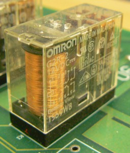
The Phase Shifters use commercial PCB mounted power relays in place of the original coaxial relays for greater reliability, lower cost, lower power consumption and smaller size (Figure 15). These advantages allowed the Phase Shifter to be extended to 6 bits precision (5.6° phase step). Use of these relays reduces the number of coaxial connectors in the signal path by 10 (minimum).
Each Phase Shifter has an “address input” connector used to give each unit it’s unique identity (location) within the array. The 100 unique “ID” plugs in the Aberystwyth system are attached to their respective mounting poles by lanyards to avoid mix-ups. This means all Phase Shifter units are identical and interchangeable. A suspected faulty unit can be easily swapped with a spare unit in a few minutes.
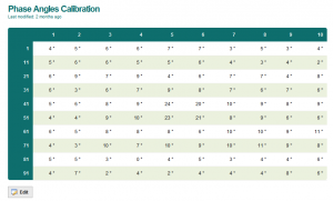
The finer phase precision allowed the addition of a phase offset table to the beam control software, this was used to compensate for the small variations in phase in the Aberystwyth RF distribution network (Figure 16).
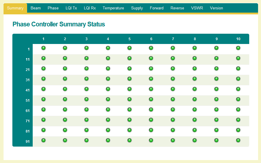
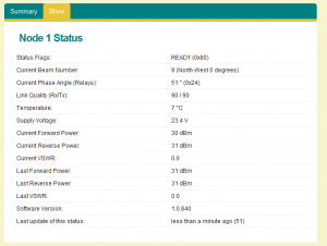
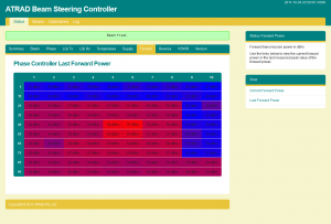
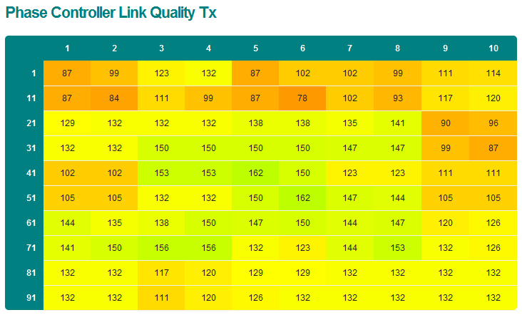
Each Phase Shifter can report internal supply voltage, temperature, forward and reverse power, and 2.4GHz control signal quality. These parameters are logged by the beam steering PC and can be displayed in graphical format providing for easy system status checks (Figures 17a to 17d). These new features help to identify and diagnose problems affecting other parts of the system, e.g. reporting if/when one of the transmitters is affected.
The Phase Shifters also include an internal 4-way Wilkinson Hybrid Power Splitter replacing the original external Splitter.
The reuse of the existing coaxial network to provide power and control communications to the new Phase Shifters removes the extra initial cost and on-going maintenance issues of a separate power and control cable network.
The improved 6-bit phase precision and flexible TCP/IP command interface mean the new system is no longer limited to 16 beam directions and can support virtually any beam direction within the capability of the antenna array geometry.
[wpcol_1quarter id=”” class=”” style=””]
[/wpcol_1quarter] [wpcol_1quarter id=”” class=”” style=””]
[/wpcol_1quarter] [wpcol_1quarter id=”” class=”” style=””]
[/wpcol_1quarter] [wpcol_1quarter_end id=”” class=”” style=””]
[/wpcol_1quarter_end]
J. D. Eastment, W. J. Bradford, D. A. Hooper, Z. A. K. Olewicz, O. T. Davies, and L. Dean. The effects of almost 20 years of operation on the performance of the Aberystwyth MST radar. In N. Swarnalingam and W. K. Hocking, editors, Proceedings of the Twelfth International Workshop on Technical and Scientific Aspects of MST Radar, pages 119-122, Ottawa, Ontario, Canada, 2010. Canadian Association of Physicists. ISBN:978-0-9867285-0-1.
Link
Richard Mayo, John Bradford, Les Dean, Jon Eastment, Marco Hess, Eric Hibbett, David Hooper, John Jacobs. Renovation of the Aberystwyth MST radar – Technical Description. MST-13 meeting.
DownloadLatest 24-hour data plot. Courtesy of the NERC MST Radar facility. Additional data can be found here.
![[http://www.mstrf.eclipse.co.uk] 24 hour data](http://www.mstrf.eclipse.co.uk/PLOTS_LATEST-24-HOURS/nerc-mstrf-radar-mst_capel-dewi_latest-24-hours_cartesian-wind-st300.png)


